
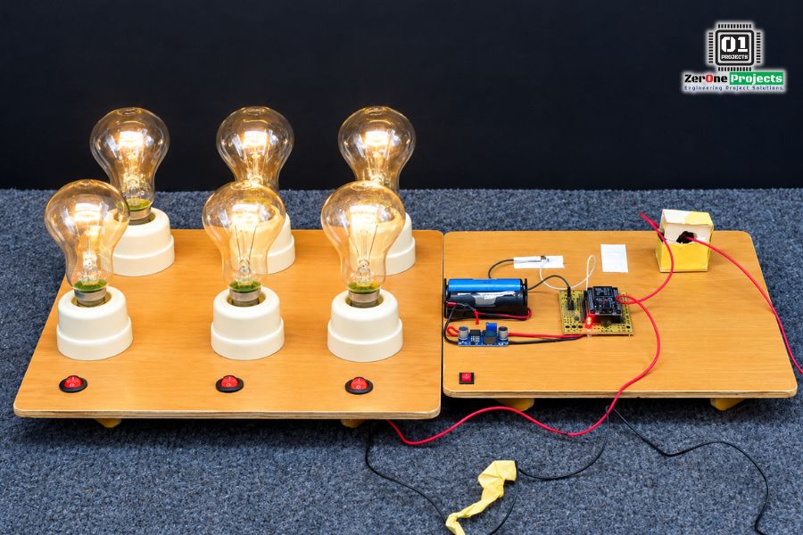
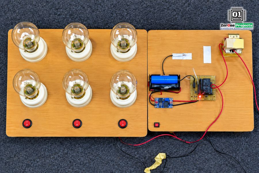
Smart Self Power IOT Based Transmission Line Current Monitoring System
Project Fee:Negotiable
Project Discount:0
Project Duration:30 Days
The Smart Self-Power IoT-Based Transmission Line Current Monitoring System is designed to monitor changes in electrical current under different load conditions using IoT technology and renewable energy. The prototype uses a current transformer (CT) sensor to measure load current, a rectifier to convert the sensor signal into a suitable form for measurement, and a NodeMCU to process the data for IoT-based monitoring. A solar panel charges the battery, while a buck converter regulates the voltage required by the NodeMCU. This project demonstrates a practical approach to current monitoring and renewable-energy-powered operation.
To monitor transmission line current under different load conditions.
To measure current changes using a CT sensor.
To display current readings through an IoT dashboard.
To power the monitoring system using solar energy.
To regulate the supply voltage using a buck converter.
To develop a cost-effective current monitoring prototype.
Developing the project concept and preparing the block diagram and circuit diagram.
Collecting the required components, including the NodeMCU, CT sensor, rectifier, solar panel, and battery.
Connecting the CT sensor and rectifier to obtain a measurable current signal.
Integrating the NodeMCU with an IoT dashboard for current monitoring.
Connecting the solar panel to charge the battery and using a buck converter to provide a suitable voltage to the NodeMCU.
Testing the system under different bulb-load conditions and observing the current readings.
NodeMCU
Current Transformer (CT) Sensor
Rectifier Circuit
Solar Panel
Rechargeable Battery
Buck Converter
AC Bulbs and Holders
IoT Monitoring Dashboard
Connecting Wires and PCB
When the AC bulb loads are switched ON or OFF, the current flowing through the load line changes.
The CT sensor detects the current flowing through the line and produces a corresponding signal.
The rectifier converts the CT sensor's AC signal into a suitable signal for the measurement circuit.
The NodeMCU processes the measured data and sends current readings to the IoT dashboard.
The solar panel charges the battery, which supplies power to the monitoring system through the buck converter.
Users can observe changes in current remotely through the IoT interface.
Real-Time Current Monitoring
IoT-Based Remote Observation
Solar-Powered Operation
Reduced Dependence on Grid Power
Load Variation Detection
Battery-Based Power Support
Regulated Voltage Supply
Improved Monitoring Convenience
Cost-Effective Prototype
Supports Smart Grid Development
The Smart Self-Power IoT-Based Transmission Line Current Monitoring System demonstrates how IoT technology and solar energy can be combined for electrical current monitoring. The prototype measures current variations under different load conditions and displays the readings through an IoT dashboard while using a solar-charged battery for power. With improved measurement calibration, data logging, and protective features, the system could be further developed for more reliable electrical monitoring applications.
The Smart Self-Power IoT-Based Transmission Line Current Monitoring System is designed to monitor changes in electrical current under different load conditions using IoT technology and renewable energy. The prototype uses a current transformer (CT) sensor to measure load current, a rectifier to convert the sensor signal into a suitable form for measurement, and a NodeMCU to process the data for IoT-based monitoring. A solar panel charges the battery, while a buck converter regulates the voltage required by the NodeMCU. This project demonstrates a practical approach to current monitoring and renewable-energy-powered operation.
To monitor transmission line current under different load conditions.
To measure current changes using a CT sensor.
To display current readings through an IoT dashboard.
To power the monitoring system using solar energy.
To regulate the supply voltage using a buck converter.
To develop a cost-effective current monitoring prototype.
Developing the project concept and preparing the block diagram and circuit diagram.
Collecting the required components, including the NodeMCU, CT sensor, rectifier, solar panel, and battery.
Connecting the CT sensor and rectifier to obtain a measurable current signal.
Integrating the NodeMCU with an IoT dashboard for current monitoring.
Connecting the solar panel to charge the battery and using a buck converter to provide a suitable voltage to the NodeMCU.
Testing the system under different bulb-load conditions and observing the current readings.
NodeMCU
Current Transformer (CT) Sensor
Rectifier Circuit
Rechargeable Battery
Buck Converter
AC Bulbs and Holders
IoT Monitoring Dashboard
Connecting Wires and PCB
When the AC bulb loads are switched ON or OFF, the current flowing through the load line changes.
The CT sensor detects the current flowing through the line and produces a corresponding signal.
The rectifier converts the CT sensor's AC signal into a suitable signal for the measurement circuit.
The NodeMCU processes the measured data and sends current readings to the IoT dashboard.
The solar panel charges the battery, which supplies power to the monitoring system through the buck converter.
Users can observe changes in current remotely through the IoT interface.
Real-Time Current Monitoring
IoT-Based Remote Observation
Solar-Powered Operation
Reduced Dependence on Grid Power
Load Variation Detection
Battery-Based Power Support
Regulated Voltage Supply
Improved Monitoring Convenience
Cost-Effective Prototype
Supports Smart Grid Development
The Smart Self-Power IoT-Based Transmission Line Current Monitoring System demonstrates how IoT technology and solar energy can be combined for electrical current monitoring. The prototype measures current variations under different load conditions and displays the readings through an IoT dashboard while using a solar-charged battery for power. With improved measurement calibration, data logging, and protective features, the system could be further developed for more reliable electrical monitoring applications.
👉 দেশের যে কোন ইঞ্জিনিয়ারিং ভার্সিটির প্রজেক্ট, প্রেজেন্টেশন, থিসিস পেপার, প্রজেক্ট বই, ইত্যাদি। সকল সমাধান পাবেন আমাদের কাছে।
🔰 ইঞ্জিনিয়ারিং ফাইনাল ইয়ার প্রজেক্টস এবং স্কুল-কলেজের ছাত্র ছাত্রীদের বিজ্ঞান মেলায় প্রতিযোগিতা করার জন্য, পছন্দের তালিকায় রাখতে পারেন আমাদের নিজিস্ব ডিজাইনের তৈরি এই ডেমো প্রজেক্ট গুলো। আমাদের রয়েছে সফলতার সাথে ১৫০০+ প্রজেক্ট সম্পন্ন করার অভিজ্ঞতা।
🔰 আপনার প্রজেক্টের আইডিয়া, সম্পূর্ণ প্রজেক্ট, প্রজেক্ট পেপার, পাওয়ার পয়েন্ট প্রেজেন্টেশন এবং আপনার প্রজেক্ট ভাইবা পর্যন্ত সকল ধরণের কারেকশন, সহযোগিতা করার জন্য আমাদের টিম আছে আপনার সাথে।
🔰 প্রতিনিয়ত আমরা আপনাদের জন্য বেস্ট সার্ভিস আর আপনাদের চাহিদা অনুযায়ী প্রজেক্ট তৈরি করে আপনাদের হাতে পৌঁছে দেওয়ার জন্য করে যাচ্ছি অক্লান্ত পরিশ্রম। আপনাদের রেসপন্সে আমরা অভিভূত।
𝐂𝐨𝐧𝐭𝐚𝐜𝐭 𝐃𝐞𝐭𝐚𝐢𝐥𝐬:
📞 01894-801150, 01886-180101
📧Email: projects.zeronebd@gmail.com
🌐Web: https://www.projects.zeronebd.com
YouTube Channel: https://www.youtube.com/c/ZerOneProjects
🏠অফিস:
প্লট-০৩, রোড -০৪, সেকশন ৬/ক
মিরপুর-২ (মিরপুর শের-ই-বাংলা স্টেডিয়ামের ৪নং গেটের বিপরীতে),
ঢাকা-১২১৬

Copyright ©2023 ZerOne IT Limited. All Rights Reserved.