
Car Speed Checker with LCD Display & Over Speed Penalty System over IoT.
Project Fee:Negotiable
Project Discount:0
Project Duration:One Month
Car Speed Checker with LCD Display and Over Speed Penalty System Over IoT.
About
This Project:
While driving on highways, drivers should not exceed the maximum speed
limit permitted for their vehicle. However, accidents keep on occurring due to
speed violations as drivers follow their speedometers and control their speed according to
them, and reduce the speed if they find it to be exceeding nd beyond their
control. A highway speed checker comes handy for the traffic police,
especially against the speed limit violators because it provides the digital
display as well as buzzing sound or alarm to detect any vehicle speed if the
vehicle exceeds the permitted speed limit.
Keeping this fact in our minds, we have come up with the project titled ‘Car
Speed Checker With LCD Display & Over Speed Penalty System Using NodeMCU ’.
The way the whole project works is that we take 220V (rms) ac power from the supply voltage and then feed it to a Switch Mode Power Supply or in short SMPS module. Basically inside the SMPS what we have is a 12V Step Down Transformer, Diodes formed in Full Wave Bridge Rectifier formation, some Capacitors, Voltage Regulator ICs and Resistors. The SMPS simply converts the 220V ac to a pure dc of 5V. The Way it happens is that when we give 220V ac as the input to the SMPS module, firstly that 220V meets the 12V Step Down Transformer and as a result, we get a 12V ac output from the Step Down Transformer. Now, this 12V ac inside the SMPS next faces the Diodes formed in Full Wave Rectifier design and the output we get from that Full Bridge Rectifier formation is a 12V pulsating dc but we need pure dc that’s why there’s a Capacitor next to the Full Wave Bridge Rectifier formation to smooth the pulsating dc into pure dc. Now, inside the SMPS up until now, what we have is a 12V pure dc but that won’t do for us because to run our Arduino Nano and other devices connected to the Arduino Nano, we need 5V dc. So for that we have a 5V Regulator IC inside the SMPS so that it can turn the 12V dc into a stable 5V dc. Now, this 5V dc is the final output of the SMPS module. So in simple words, the SMPS turns the 220V ac into 5V dc for our use. We will use this 5V dc output from the SMPS to run our Arduino Nano and the buzzer aside from these two, all the other circuit components like IR Sensors, NodeMCU, LCD Display, Servo Motor are going to take voltage from the Arduino Nano to power themselves.

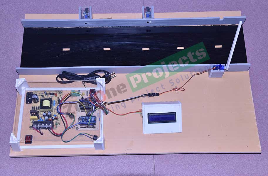
We have placed two Infrared Sensors (IR) apart from each other at a known distance which can observed from the above picture. Whenever a car crosses the IR1, it detects the car and sends a signal to the Arduino Nano and the Arduino Nano starts calculating time and when that same car crosses the IR2 sensor, the IR2 sensor after detecting the car, sends signal to the Arduino Nano and the Nano immediately stops calculating time. So, now we have a recorded ‘Time’ with us and also the ‘Distance’ between the two sensors is known to us and thus we can calculate the speed of the car using the formula, Speed= Distance/Time. The Arduino Nano has been programmed to do that and after calculating the speed of the car, it displays that information on the LCD Display. A threshold value or maximum value of speed has been given to the Arduino Nano so that if the speed of the car exceeds that maximum value, immediately three things will happen, firstly the Buzzer will start to make sounds, secondly, a barricade will be placed in front of the car to slow it down (In our design model, we have used a Servo Motor to do that) and lastly, the NodeMCU will wirelessly transmit information using an Internet connection to a specific mobile phone (In practice, this mobile phone will belong to a traffic police officer). We should keep in mind that only if the car exceeds the given speed limit only then the above three things will happen otherwise only the car’s speed will be shown on the LCD display board.

Figure: Block Diagram of Car Speed Checker with LCD Display and Over Speed Penalty System Over IoT.
Required Instrument:
-
Arduino Nano.
-
Node MCU.
-
IR Sensor.
-
LCD Display.
-
Buzzer
-
SMPS.
-
Switch.
-
Servo Motor.
Advantages:
There are many advantages of the project. Some of these are given below:
•
This
project can be implemented easily and requires less maintenance
•
Works
instantly so that actions can be taken on the right time
•
The
items needed to build this project are small in size and easy to get
•
The
whole system runs automatically so it’s really user friendly
Applications:
There are many practical applications of
the project. Some of these are given below:
•
It can be used in roads
where maintaining speed is essential such as public places, hospitals,
educational institutes etc.
•
It can be used in places
where car accidents occur frequently
•
It can be used in highways
so that vehicles do not go beyond a level of speed where it becomes dangerous
for them
Any modification of this project can be done as per your requirement. We will make the project according to your needs. Contact us with your any innovative engineering projects idea. We will help you to implement your project.
? Office: Road#04, Plot#03, Sec#6/Ka, Mirpur-2, Dhaka-1216 (Opposite of the Mirpur Cricket Stadium 4 No. Gate.) | ? ?e-Mail : projects.zeronebd@gmail.com ☎️Contact: 01676 99 80 99 , 01714 80 84 02 |
Copyright ©2023 ZerOne IT Limited. All Rights Reserved.